2017年10月 USB-TTL変換を追加
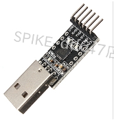
・CP2102(6pin)
2016年12月 USB-TTL変換を追加
・CH340(6pin)
・PL2303(4pin)
・PL2303(5pin)
準備
◆Arduino IDE (PCにインストール無料)

◆Arduino Uno(ピンヘッダー同梱) (360円+送料170円)
※無くても可

◆Arduino IDE(PC)と Arduino Uno をつなぐUSBケーブル(100円+送料170円)

◆Arduino Pro Mini ATMEGA328P 5V 16MHz(320円+送料170円)


◆Arduino IDE(PC)とUSBシリアル変換モジュール(FT232RL)をつなぐMiniUSBケーブル(100円)

cp2102 TTL is 3.3V。but,Absolute Maximum Ratings is 5.8V。


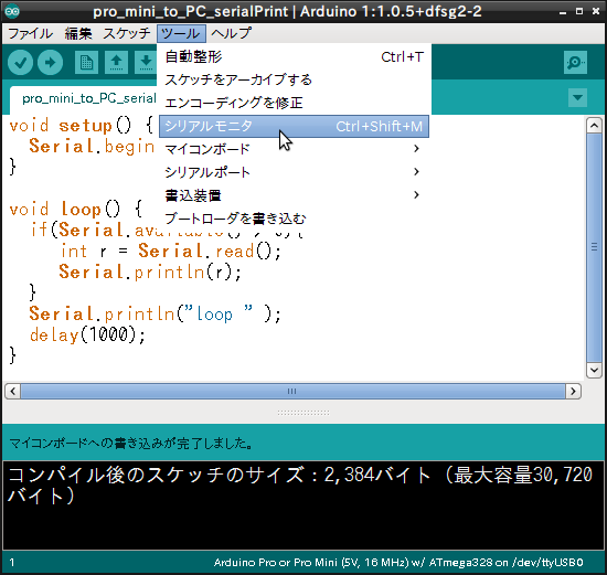
ツール>マイコンボード>Arduino Uno


Arduino as ISP


◆しかし、but


(スケッチを書き込めます)
(This has DTR pin. can write a sketch)
※cp2102のTXD、RXDの入出力は3.3V。しかし、絶対最大定格は5.8V。
cp2102 TTL is 3.3V。but,Absolute Maximum Ratings is 5.8V。

・CH340
(スケッチは書き込めません、通信はできます)
(This doesn't have a DTR pin. can not write a sketch)

}
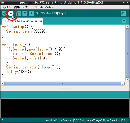
void loop() {
if(Serial.available() > 0){
int r = Serial.read();
Serial.println(r);
}
Serial.println("loop " );
delay(1000);
}


 input the a and send


(スケッチを書き込めます)
(This has DTR pin. can write a sketch)
※cp2102のTXD、RXDの入出力は3.3V。しかし、絶対最大定格は5.8V。
cp2102 TTL is 3.3V。but,Absolute Maximum Ratings is 5.8V。


・PL2303(5pin)
(スケッチは書き込めません、通信はできます)
(This doesn't have a DTR pin. can not write a sketch)

}
void loop() {
if(Serial.available() > 0){
int r = Serial.read();
Serial.println(r);
}
Serial.println("loop " );
delay(1000);
}

input the a and send

(スケッチを書き込めます)
(This has DTR pin. can write a sketch)
※cp2102のTXD、RXDの入出力は3.3V。しかし、絶対最大定格は5.8V。
cp2102 TTL is 3.3V。but,Absolute Maximum Ratings is 5.8V。

・PL2303
(スケッチは書き込めません、通信はできます)
(This doesn't have a DTR pin. can not write a sketch)

・2sk30A
何かレベル変換できるもの

・レギュレータ(Voltage Regulator )
何か電圧変換できるもの


}
void loop() {
if(Serial.available() > 0){
int r = Serial.read();
Serial.println(r);
}
Serial.println("loop " );
delay(1000);
}


・CP2102(6pin)
2016年12月 USB-TTL変換を追加
・CH340(6pin)
・PL2303(4pin)
・PL2303(5pin)
準備
◆Arduino IDE (PCにインストール無料)
◆Arduino Uno(ピンヘッダー同梱) (360円+送料170円)
※無くても可

◆Arduino IDE(PC)と Arduino Uno をつなぐUSBケーブル(100円+送料170円)


◆Arduino IDE(PC)とUSBシリアル変換モジュール(FT232RL)をつなぐMiniUSBケーブル(100円)

工作開始
方法1: (FTDI FT232RL) 又は (cp2102) を使用
※cp2102のTXD、RXDの入出力は3.3V。しかし、絶対最大定格は5.8V。
◆つなぎましょう.
It lights up without anything
何もしなくともLチカしている

◆Arduino Pro mini に スケッチを書き込みましょう
void setup() {
pinMode(13, OUTPUT);
}
}
void loop() {
digitalWrite(13, HIGH);
delay(100);
digitalWrite(13, LOW);
delay(100);
}
digitalWrite(13, HIGH);
delay(100);
digitalWrite(13, LOW);
delay(100);
}
Ardduino Pro or Pro Mini(5V, 16MHz)W/ATmega328
→
成功、 success

方法2:Arduino Uno を使用
◆つなぎましょう.

◆Arduino Unoに ArduinoISP を書き込みましょう
ファイル>スケッチの例>ArduinoISP


ツール>マイコンボード>Arduino Uno

→

◆つなぎましょう.
◆Arduino Pro mini に スケッチを書き込みましょう
void setup() {
pinMode(13, OUTPUT);
}
pinMode(13, OUTPUT);
}
void loop() {
digitalWrite(13, HIGH);
delay(100);
digitalWrite(13, LOW);
delay(100);
}
digitalWrite(13, HIGH);
delay(100);
digitalWrite(13, LOW);
delay(100);
}
Ardduino Pro or Pro Mini(5V, 16MHz)W/ATmega328

Arduino as ISP

→
失敗エラー、error
avrdude: stk500_getsync() attempt 1 of 10: not in sync:resp=
そこで、Well
成功、 success

再び (FTDI FT232RL) 又は (cp2102)を使用、again with the FTDI FT232RL or cp2102

失敗エラー、error
◆そこで、well
ブートローダ書き込む、write a boot loader

Ardduino Pro or Pro Mini(5V, 16MHz)W/ATmega328


Arduino as ISP


◆再び、retry
成功、 success
方法3: (CH340) と (FTDI FT232RL) 又は (cp2102)を使用
・ FTDI FT232RL(スケッチを書き込めます)
(This has DTR pin. can write a sketch)
※cp2102のTXD、RXDの入出力は3.3V。しかし、絶対最大定格は5.8V。
・CH340
(スケッチは書き込めません、通信はできます)
(This doesn't have a DTR pin. can not write a sketch)
◆最初に、first
void setup() {
Serial.begin(9600);}
void loop() {
if(Serial.available() > 0){
int r = Serial.read();
Serial.println(r);
}
Serial.println("loop " );
delay(1000);
}
◆次に、next
成功、 success.
ASCII code of the a is 97
ASCII code of the CR is 13
ASCII code of the LF is 10

方法4: FTDI FT232RL と PL2303(5pin) を使用
・ FTDI FT232RL(スケッチを書き込めます)
(This has DTR pin. can write a sketch)
※cp2102のTXD、RXDの入出力は3.3V。しかし、絶対最大定格は5.8V。
・PL2303(5pin)
(スケッチは書き込めません、通信はできます)
(This doesn't have a DTR pin. can not write a sketch)
◆最初に、first
void setup() {
Serial.begin(9600);}
void loop() {
if(Serial.available() > 0){
int r = Serial.read();
Serial.println(r);
}
Serial.println("loop " );
delay(1000);
}
◆次に、next
成功、 success.
ASCII code of the a is 97
ASCII code of the CR is 13
ASCII code of the LF is 10

方法5:( FTDI FT232RL 又は cp2102) と (PL2303) と (2sk30A(N-JFET) )と (レギュレータ) と (抵抗) を使用
・ FTDI FT232RL(スケッチを書き込めます)
(This has DTR pin. can write a sketch)
※cp2102のTXD、RXDの入出力は3.3V。しかし、絶対最大定格は5.8V。
・PL2303
(スケッチは書き込めません、通信はできます)
(This doesn't have a DTR pin. can not write a sketch)
・2sk30A
何かレベル変換できるもの

・レギュレータ(Voltage Regulator )
何か電圧変換できるもの

・抵抗
何か pull up できるもの

◆最初に、first
void setup() {
Serial.begin(9600);}
void loop() {
if(Serial.available() > 0){
int r = Serial.read();
Serial.println(r);
}
Serial.println("loop " );
delay(1000);
}
◆次に、next
input the a and send
成功、 success.
ASCII code of the a is 97
ASCII code of the CR is 13
ASCII code of the LF is 10

0 件のコメント:
コメントを投稿