準備
◆Arduinoソフト (PCにインストール無料)

◆Arduinoハード(ピンヘッダー同梱) (360円+送料170円)

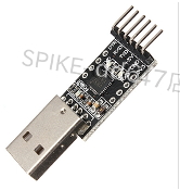
◆Arduinoソフト(PC)と Arduinoハード をつなぐUSBケーブル(100円+送料170円)

◆ GY-271 HMC5883L 3軸磁気センサー(380円+送料170円)

◆ ブレッドボード・ジャンパーワイヤ40本(100円+送料170円)


◆ハード(マイコンボード)に Arduino Uno を選びましょう

◆Arduinoソフトにスケッチを書きましょう

/*
An Arduino code example for interfacing with the HMC5883
by: Jordan McConnell
SparkFun Electronics
created on: 6/30/11
license: OSHW 1.0, http://freedomdefined.org/OSHW
Analog input 4 I2C SDA
Analog input 5 I2C SCL
*/
#include <Wire.h> //I2C Arduino Library
#define address 0x1E //0011110b, I2C 7bit address of HMC5883
void setup(){
//Initialize Serial and I2C communications
Serial.begin(9600);
Wire.begin();
//Put the HMC5883 IC into the correct operating mode
Wire.beginTransmission(address); //open communication with HMC5883
Wire.write(0x02); //select mode register
Wire.write(0x00); //continuous measurement mode
Wire.endTransmission();
}
void loop(){
int x,y,z; //triple axis data
//Tell the HMC5883 where to begin reading data
Wire.beginTransmission(address);
Wire.write(0x03); //select register 3, X MSB register
Wire.endTransmission();
//Read data from each axis, 2 registers per axis
Wire.requestFrom(address, 6);
if(6<=Wire.available()){
x = Wire.read()<<8; //X msb
x |= Wire.read(); //X lsb
z = Wire.read()<<8; //Z msb
z |= Wire.read(); //Z lsb
y = Wire.read()<<8; //Y msb
y |= Wire.read(); //Y lsb
}
//Print out values of each axis
Serial.print("x: ");
Serial.print(x);
Serial.print(" y: ");
Serial.print(y);
Serial.print(" z: ");
Serial.println(z);
delay(250);
}
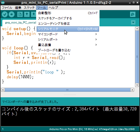
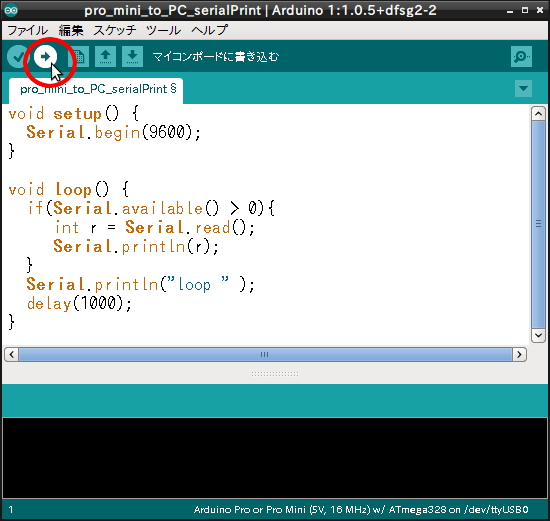
◆Arduinoハード(マイコンボード)にスケッチを書き込みましょう

◆シリアルモニタで見てみましょう


◆Arduinoソフト (PCにインストール無料)
◆Arduinoハード(ピンヘッダー同梱) (360円+送料170円)

◆Arduinoソフト(PC)と Arduinoハード をつなぐUSBケーブル(100円+送料170円)


◆ ブレッドボード・ジャンパーワイヤ40本(100円+送料170円)

工作開始
◆全てつなぎましょう◆ハード(マイコンボード)に Arduino Uno を選びましょう

◆Arduinoソフトにスケッチを書きましょう
/*
An Arduino code example for interfacing with the HMC5883
by: Jordan McConnell
SparkFun Electronics
created on: 6/30/11
license: OSHW 1.0, http://freedomdefined.org/OSHW
Analog input 4 I2C SDA
Analog input 5 I2C SCL
*/
#include <Wire.h> //I2C Arduino Library
#define address 0x1E //0011110b, I2C 7bit address of HMC5883
void setup(){
//Initialize Serial and I2C communications
Serial.begin(9600);
Wire.begin();
//Put the HMC5883 IC into the correct operating mode
Wire.beginTransmission(address); //open communication with HMC5883
Wire.write(0x02); //select mode register
Wire.write(0x00); //continuous measurement mode
Wire.endTransmission();
}
void loop(){
int x,y,z; //triple axis data
//Tell the HMC5883 where to begin reading data
Wire.beginTransmission(address);
Wire.write(0x03); //select register 3, X MSB register
Wire.endTransmission();
//Read data from each axis, 2 registers per axis
Wire.requestFrom(address, 6);
if(6<=Wire.available()){
x = Wire.read()<<8; //X msb
x |= Wire.read(); //X lsb
z = Wire.read()<<8; //Z msb
z |= Wire.read(); //Z lsb
y = Wire.read()<<8; //Y msb
y |= Wire.read(); //Y lsb
}
//Print out values of each axis
Serial.print("x: ");
Serial.print(x);
Serial.print(" y: ");
Serial.print(y);
Serial.print(" z: ");
Serial.println(z);
delay(250);
}
◆Arduinoハード(マイコンボード)にスケッチを書き込みましょう
◆シリアルモニタで見てみましょう

別のソフトを使って出力されたX,Y,Zをプロットしてみると(Plot value)